480 Volt Motor Starter Wiring Diagram - View 23 Square D Single Phase Motor Starter Wiring Diagram. Wiring diagram book a1 15 b1 b2 16 18 b3 a2 b1 b3 15 supply voltage 16 18 l m h 2 levels b2 l1 f u 1 460 v f u 2 l2 l3 gnd h1 h3 h2 h4 f u 3 x1a f u 4 f u 5 x2a r power on optional x1 x2115 v. Industry wide the 480 volt 3 phase motor is the most common of all electric motors. Effectively read a cabling diagram, one has to learn how typically the components in the system operate. When a logic signal is applied to the forward terminal, the gn0 switches l1 and l2 directly to. In western canada 347/600v is common.
Wiring diagrams do not show the operating mechanism since it is not electrically controlled. 460 v 11 16 480 v 12 16 three phase loads open delta connection an open delta connection is for three wire power loads only. Rewire red wires at coil. Kindly email me the diagrams for star deltor and direct online for a 3speed 1directon 3ph motor, have two of them in a bow cutter. Types of electrical wiring electrical circuit diagram electrical projects single phase transformer car drawing easy ac capacitor trailer light wiring ferrari convertible symbol drawing.
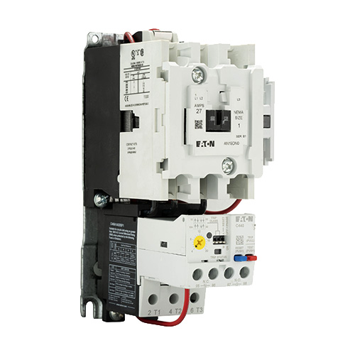
Freedom Nema Motor Control Contactors And Starters Eaton from www.eaton.com When a logic signal is applied to the forward terminal, the gn0 switches l1 and l2 directly to. Effectively read a cabling diagram, one has to learn how typically the components in the system operate. For example , if a module is usually powered up also it sends out a new signal of 50 percent the voltage plus the technician does not know this, he'd think he offers an issue, as he or she would expect the. L1 is line 1 in and should be connected to one of the hot wires, l2 is line 2 in. (remove red wire connecting x2 to l2). Time lapse of schematic diagram drawn into a wire diagram and the wiring of the magnetic motor starter. Typically an induction motor will run by a voltage of 230 volt or 460 volt, 3 phase 60 hz in usa and be controlled by a control voltage of 115 volt ac or 24 volt dc. They are used in applications which do not require undervoltage protection.
When a logic signal is applied to the forward terminal, the gn0 switches l1 and l2 directly to.
When a logic signal is applied to the forward terminal, the gn0 switches l1 and l2 directly to. 480v 3 phase motor wiring diagram. Always use wiring diagram supplied on motor nameplate. The supply voltage is either 240 volts alternating current vac or 480 vac. Water pump controller with float switchauto manual connection of water pump motor w. This entire assembly consisting of contactor overload block control power transformer power fuses or alternatively a circuit breaker and associated components is informally referred to as a bucket. Time lapse of schematic diagram drawn into a wire diagram and the wiring of the magnetic motor starter. Electrical motors 12 lead, dual voltage, wye start/delta run, both voltages or 6 lead, single voltage, wye start/delta run motors designed by us motors for wye start, delta run may also be used for across the line starting using only the delta connection. One contactor burnt for high speed and a replced contactor does not engange, originally the coils re fed with a nutural and the one i replaced is only working with a phase. 460 v 11 16 480 v 12 16 three phase loads open delta connection an open delta connection is for three wire power loads only. Fiber optic cable electrical connections motor 3ct to v separate control * ot is a switch that opens when an overtemperature condition exists (type mfo and mgo only) t1 t3 wiring diagram. (remove red wire connecting x2 to l2). For example , if a module is usually powered up also it sends out a new signal of 50 percent the voltage plus the technician does not know this, he'd think he offers an issue, as he or she would expect the.
Diagram motor control wiring 👉 note how a control power transformer steps down the 480 volt ac to provide 120 volt ac power for the contactor coil to operate on. In larger facilities the voltage is 277/480 volt and used to power single phase 277 volt lighting and larger hvac loads. A lead wye start/delta run motor has the ability to meet several starting wye delta starter or by a series of contactors in a control circuit. Always use wiring diagram supplied on motor nameplate. They are used in applications which do not require undervoltage protection.
480 Motor Starter Wiring Diagram 3 Phase Wiring For Dummies Understanding Motor Connections from syv.praysreckless.pw Typical wiring diagrams for push button control stations. 240 volt, 1 phase motors should use a 2 pole starter. How the wires are interconnected dictates the voltage being supplied to the motor. Types of electrical wiring electrical circuit diagram electrical projects single phase transformer car drawing easy ac capacitor trailer light wiring ferrari convertible symbol drawing. Typical wiring diagrams always use wiring diagram supplied on motor nameplate connection diagrams co4 460 12 leads part winding weg three phase motors 460 volts 12 lead part winding 12. Coil above is wired for 230 v to pump motor, 120 v from isotrol or dispenser switch. Water pump controller with float switchauto manual connection of water pump motor w. This entire assembly consisting of contactor overload block control power transformer power fuses or alternatively a circuit breaker and associated components is informally referred to as a bucket.
They are used in applications which do not require undervoltage protection.
Industry wide the 480 volt 3 phase motor is the most common of all electric motors. (remove red wire connecting x2 to l2). This wiring should not be used on 240 volt circuits. 12 leads 3 phase high volts delta connected wiring configuration diagram electrical schematic diagram of a delta configured 12 leads motor so connected a lternatively, discover how to power your home. V motor starter wiring diagram together with volt 3 phase wiring diagram besides along with wiring diagram view contactor start stop along with how. Typical wiring diagrams for push button control stations. Damage will occur if the motor is operated with load for more. T1 is motor 1 out and goes from the starter to the motor. Wiring diagrams do not show the operating mechanism since it is not electrically controlled. For example , if a module is usually powered up also it sends out a new signal of 50 percent the voltage plus the technician does not know this, he'd think he offers an issue, as he or she would expect the. How the wires are interconnected dictates the voltage being supplied to the motor. They are used in applications which do not require undervoltage protection. Orange red blue blue black t1 l1 l1 l2 l3 l2 l3 x2 t2 t3 to 208/230v supply coil 3421 3 to.
An outlet is defined by the nec as a point in the wiring system at which current is taken to utilization equipment. Rewire red wires at coil. This wiring should not be used on 240 volt circuits. They are used in applications which do not require undervoltage protection. Effectively read a cabling diagram, one has to learn how typically the components in the system operate.
The Difference Between Contactors And Motor Starters And Reduced Voltage Starters from 3l4sbp4ao2771ln0f54chhvm-wpengine.netdna-ssl.com 460 v 11 16 480 v 12 16 three phase loads open delta connection an open delta connection is for three wire power loads only. Time lapse of schematic diagram drawn into a wire diagram and the wiring of the magnetic motor starter. Types of electrical wiring electrical circuit diagram electrical projects single phase transformer car drawing easy ac capacitor trailer light wiring ferrari convertible symbol drawing. How the wires are interconnected dictates the voltage being supplied to the motor. Always use wiring diagram supplied on motor nameplate. In western canada 347/600v is common. Wiring diagram 3 wiring diagram 4. This entire assembly consisting of contactor overload block control power transformer power fuses or alternatively a circuit breaker and associated components is informally referred to as a bucket.
An outlet is defined by the nec as a point in the wiring system at which current is taken to utilization equipment.
Kindly email me the diagrams for star deltor and direct online for a 3speed 1directon 3ph motor, have two of them in a bow cutter. 480 3 phase motor wiring data wiring diagram blog plex 230 volt 3 phase motor wiring diagram 480 3 phase motor 480 volt 6 lead motor 480 3 phase three phase wiring diagrams always use wiring diagram supplied on. 240 volt, 1 phase motors should use a 2 pole starter. In larger facilities the voltage is 277/480 volt and used to power single phase 277 volt lighting and larger hvac loads. The supply voltage is either 240 volts alternating current vac or 480 vac. How the wires are interconnected dictates the voltage being supplied to the motor. Wiring diagram 3 wiring diagram 4. Orange red blue blue black t1 l1 l1 l2 l3 l2 l3 x2 t2 t3 to 208/230v supply coil 3421 3 to. Typical wiring diagrams for push button control stations. This wiring should not be used on 240 volt circuits. This entire assembly consisting of contactor overload block control power transformer power fuses or alternatively a circuit breaker and associated components is informally referred to as a bucket. (remove red wire connecting x2 to l2). Water pump controller with float switchauto manual connection of water pump motor w.
When a logic signal is applied to the forward terminal, the gn0 switches l1 and l2 directly to 480 volt motor wiring. In this case, neutral white is carried through to the motor bypassing the starter altogether.
480 Volt Motor Starter Wiring Diagram - View 23 Square D Single Phase Motor Starter Wiring Diagram. There are any 480 Volt Motor Starter Wiring Diagram - View 23 Square D Single Phase Motor Starter Wiring Diagram in here.